Mike Silvers, CPRC, Owner, Silvers Systems Inc. and FRSA Technical Director - October 2026
With the implementation of the 2026 Ninth Edition Florida Building Code (FBC) quickly approaching on December 31, 2026, Florida’s roofing industry, like many others, is trying to grasp the recent code changes and figure out just what impact they will have. Among the most concerning is the new requirement for hip and ridge flashing installation methods for metal roof coverings to be tested. This was added to the code after many reports of major damage caused by flashing failures at these locations, often during less than design wind speed events. To better understand the issue, let’s first look at the actual new code language shown in blue text and underscored both in the Building and Residential volumes.
2026 Florida Building Code, Building, Ninth Edition
CHAPTER 15 ROOF ASSEMBLIES AND ROOFTOP STRUCTURES
SECTION 1504 – PERFORMANCE REQUIREMENTS
1504.3.1: Other roof systems
1504.3.1.1 Metal hip and ridge covers.
Metal roof hip and ridge covers shall be tested for uplift resistance in accordance with ANSI/MCA FTS-1.
2026 Florida Building Code, Residential, Ninth Edition
CHAPTER 9 ROOF ASSEMBLIES SECTION R905 – REQUIREMENTS FOR ROOF COVERINGS
905.10: Metal roof panels.
R905.10.4.1 Metal hip and ridge covers.
Metal roof hip and ridge covers shall be tested for uplift resistance in accordance with ANSI/MCA FTS-1.
The code clarifies that when hip and ridge covers are made of metal they are flashing and must be corrosion resistant and comply with Table 1503.2 Metal Flashing Material, below.
2026 Florida Building Code, Building, Ninth Edition
CHAPTER 15 ROOF ASSEMBLIES AND ROOFTOP STRUCTURES
1503.2 Flashing.
Flashing shall be used to seal roofing systems, where the system is interrupted or terminated and shall be installed in such a manner to prevent moisture entering through the roof system and components at intersections with walls and penetrations through the roof system.
1503.2.1 Locations.
Flashing shall be installed at wall and roof intersections, at roof edges around roof openings, penetrations and where there is a change in roof slope or direction or a change of roof covering types. Where flashing or other components are metal, the metal shall be corrosion resistant with a thickness of not less than provided in Table 1503.2 or incompliance with RAS 111.
Exceptions:
1. This requirement does not apply to hip and ridge junctions on steep slope roof coverings (2/12 or greater) other than those made of metal.
2. This requirement does not apply where there is a change in direction or roof slope of less than 25 degrees in low slope roof coverings (less than 2/12).
Due to these code changes, we now have an additional requirement: to comply with ANSI/MCA FTS-1. In practice, metal flashings are often fabricated by or for the roofing contractor with profiles and dimensions that are adjusted depending on job conditions or desired functionality. Hip and ridge covers are often fabricated from metal flashing material (sheets or coils) according to manufacturer’s installation instructions. So, will this testing requirement change that? To understand what should be required it helps to look at the test method itself, which is included in the code as a reference standard. Below, only the portions applicable to hip and ridge are shown. (Note: I seldom dive into a test method to this degree. I hope this will help reinforce my concern.)
ANSI/MCA FTS-1-2019
Test Method for Wind Load Resistance of Flashings Used with Metal Roof Systems (portions of the test method)
1.0 Scope (portions of)
1.1 This test method evaluates the wind load resistance of flashings to be installed at the roof perimeter and roof plane transitions of metal roof systems by testing the flashing and its attachment to the supporting structure using line loads.
1.3 This test method provides a standard procedure to demonstrate wind load resistance under uniform line load. This procedure is intended to represent the effects of uniform loading on exposed elements on a building surface. Two methods of testing are provided:
1. Face Load and
2. Face Load and Top Load.
3.0 Terminology (portions of)
Failure – fracture, disengagement or unrestrained deformation of components, including fasteners, such that the specimen is not capable of resisting additional load.
Specimen – the entire assembled unit submitted for testing.
Sustained load – a load resisted for specified time.
Test cycle – a series of increasing, sustained loads.
Ultimate load – the maximum sustained load resisted by the specimen.
5.0 Summary of Test Method
5.1 This test method shall include all of the following: (1) attachment of the stiffening plate or other test apparatus components to the flashing specimen as needed, (2) attachment of the flashing specimen to the bed of the test apparatus, (3) application of a series of uniform line loads to the test specimen and (4) observation and recording of the loads resisted and mode or modes of failure of the test specimen.
5.2 The increments of load application shall be chosen so that results from a minimum of four sustained loads are recorded. If failure occurs before a minimum of four loads have been sustained, the test shall be deemed invalid.
 6.0 Apparatus
6.1 Description of Apparatus
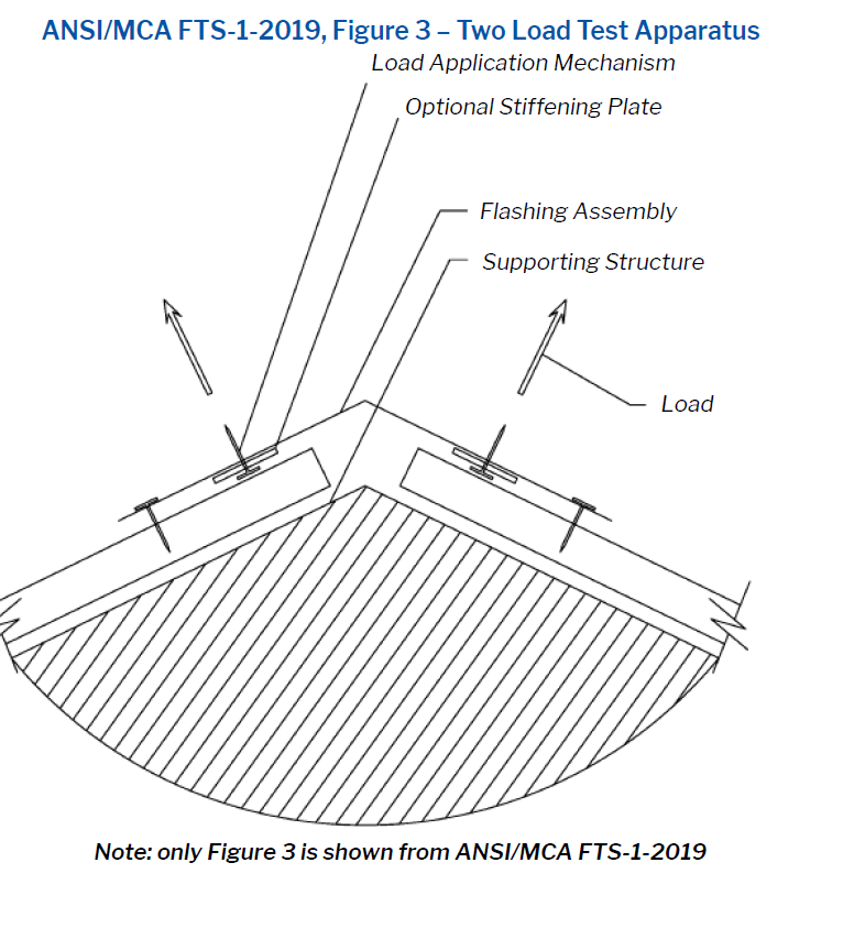
The apparatus for two load tests shall include the major components shown in Figure 2 and Figure 3. The Optional Stiffening Plate shown in these figures, if used, shall be no wider than 2” (51 mm) and no thicker
than 1/8” (3.2 mm). Figures 1, 2 and 3 indicate how loads are applied to various generic flashing configurations. Actual flashing and configuration connection shall be per the design and manufacture of the flashing to be tested.
6.2 Supporting Structure
The supporting structure shall be representative of field conditions and sized to allow the secure attachment of the specimen. Anchorage shall be required to hold the supporting structure in place while load is applied during the test. The supporting structure shall be representative of field conditions.
6.3 Load Application System (portions of)
6.3.1 The load application system shall consist of a tensile tester or other device capable of providing concentrated load and fitted with a load cell capable of indicating loads of at least the anticipated ultimate load.
6.3.2 The load application system shall be attached to the specimen in the center of the tested face and shall be capable of uniformly distributing the load to the specimen. The spacing of the specimen attachment to the load application system shall be no greater than 12 inches (300 mm) on center. The load application system shall be attached to the face centered on its width.
7.0 Test Specimen (portions of)
7.2 The flashing specimen shall be a minimum of 120 inches (3000 mm) in length, without laps in the flashing, unless the flashing is only produced in lengths less than 120 inches (3000 mm).
7.4 The minimum number of specimens shall be based on the number of load cases and test cycles required for the flashing. Three test cycles shall be performed for each load case. A new specimen shall be used for each test cycle.
7.4.2 For flashings with two exposed faces, one load case shall be required; therefore, three specimens are required. Loads shall be applied to the two faces simultaneously.
Loads shall be applied with a ratio of 2 psf (96 Pa) vertical to 1 psf (48 Pa) horizontal. If both faces are expected to receive approximately equal loading in field applications (e.g. ridge cap), then both faces shall
be tested with equal load simultaneously. The Two Load Test Apparatus shall be employed for flashings in this category. Load shall be applied perpendicular to the face.
8.0 Loading Procedure (portions of)
8.1 Orientation
The test set up shall be oriented such that gravity shall not have an undue influence on the test other than that experienced by in-place field applications. Only loads resisted by the specimen shall be included in the reported loads.
8.2 Procedure
This procedure shall be designed to produce a test cycle with a minimum of four sustained loads.
8.2.1 The typical loading cycle shall consist of two phases: a load phase and an unload phase.
8.2.2 The load phase shall apply the line loading in increasing magnitudes. The first loading shall be at one third of the anticipated ultimate load. Subsequent loadings shall be increased by up to one sixth of the anticipated ultimate load. For loads of up to 150 psf (7.2 kPa), the load shall be achieved within 1 minute. For loads greater than 150 psf (7.2 kPa), the load shall be achieved within 2 minutes. Each loading shall be held for at least 1 minute.
8.2.4 For flashings loaded on two separate faces simultaneously, the loading shall progress as described above based upon the anticipated ultimate vertical load (applied to the more horizontal surface).
8.2.5 The test shall be concluded when any of the following happen: the specimen fails, the capacity of the test apparatus is reached, or at the direction of the party conducting the test. Failure in the specimen shall be when any of the following conditions occur:
1 ) Fastener failure (ex. pull-out, pull-over or breakage),
2) Unlatching of a panel or flashing,
3) Component failure (ex. rupture, tearing or cracking).
8.2.6 A minimum of four sustained loads shall be recorded before a test cycle is concluded. If the specimen fails before four sustained loads are recorded the test cycle shall be deemed invalid and shall be repeated with a lower anticipated ultimate load that will yield four sustained loads.
9.0. Test Report
9.1 Date of test and date of report shall be included in the test report along with the name of the testing organization and location. The observers, their qualifications and affiliation shall be included.
9.2 The test report shall describe the specimen, including the manufacturer, location of manufacture and dimensions. The testing equipment including load cell and load application device shall be described.
9.3 The test report shall include cross-section drawings of the specimen including flashing, panels, panel attachment method and supporting structure. The drawings shall identify type, location and spacing of fasteners and show how and where the test apparatus is attached to the specimen.
9.5 The test report shall include the measured thickness and yield strength of the specimen.
9.6 Tabulation of the loadings and load durations, including the anticipated ultimate load, shall be included in the test report.
9.7 The test report shall include visual observations including failure mode, the sustained loads applied, and the ultimate loads. The ultimate loads from the performed test cycles shall be averaged and recorded as the test result.
9.8 The test report shall include a statement that the test(s) were conducted in accordance with this test method, noting any deviations.
To better understand the test method, see the ridge detail graphic and the photos on page 22 that were reproduced with permission of MCA, ATAS International, MBMA and Farabaugh Engineering and Testing; some of which are represented by the code modification’s proponent.
The ridge detail on the left side of the peak (standard detail) is similar to many manufacturers’ existing hip and ridge flashing installation instructions. On the right side of the peak (Tested Detail) notice the angled Z closure support, which from my observations, is unusual. Also note the location of the rivet which is very close to the edge of the cover and the typical eave Z closure. The rivet location is, in my opinion, a weak point. As seen in the pictures, it does little to prevent the hem from unfolding and, so, disengaging from the typical Z closure’s flange. Also, due to the rivets' closeness to the edge, it leads to pull-through of the hole in the flange, adding to the eventual failure.
I point this out not as a critique of this particular design but to demonstrate the importance of the attested design chosen by the manufacturer of the roof covering. The details as tested should be shown in the manufacturer’s installation instructions. The instructions should state compliance with the standard and the uplift resistance achieved in psf. This information is needed to ensure that uplift resistance of the flashing meets or exceeds the codes wind resistance requirements established in ASCE 7.
This test method is not overly complicated as test standards go. It has not been widely used but clearly has been done. I’m surprised by the apparent lack of tested installation instructions despite the fact that the implementation date is quickly approaching. Hopefully, the industry can respond in time. To say we must expedite this is an understatement – and we
don't need unnecessary bureaucracy to slow us down. These flashing details have existed as installation instructions for decades. The only difference now will be a requirement for them to have been tested.
All that contractors need is the information mentioned earlier: demonstrated compliance with the test standard and the pressure resisted. I hope we are not toasting the New Year and preparing for a new code without a resolution to this uncertainty.
FRM
Mike Silvers, CPRC is Owner of Silvers Systems Inc. and is consulting with FRSA as Director of Technical Services. Mike is an FRSA Past President, Life Member and Campanella Award recipient and brings over 50 years of industry knowledge and experience to FRSA’s team.
